Bends in Drilled Circular Passages
Drill Tip to Drill Tip Relationship
VEST research indicates that a good bend design is where the drill-tips are “blended”.
A smooth blending of surfaces is more important than extra volume in the holes.
Intentional or accidental extension of drill points past the opposite edge of the connecting hole results in poor fluid flow. This is detrimental to energy efficiency of the manifold.
|
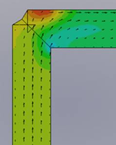
Fig 1a |
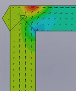
Fig 1b |
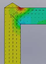
Fig 1c |
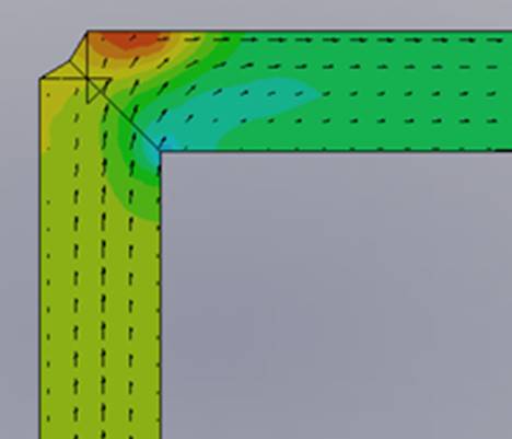
Fig 1d |
Finite Element Analysis based simulation of flow in drilled circular passages show the impact of different bend geometry on the energy loss across the bend. The images in Figure 1 show different geometry for bends.
The velocity vectors in Figure 1d show an anti-clockwise vortex formed in extended drill spaces. This results in higher energy drop.
The relative energy loss for each geometry is tabulated below:
|
|
State |
Energy Drop |
|
a |
MDTools - "Connect to Cavity" |
35 |
|
b |
Outlet Extended |
35 |
|
c |
Inlet Extended |
44 |
|
d |
Both Extended |
48 |