Machining Callout Tab
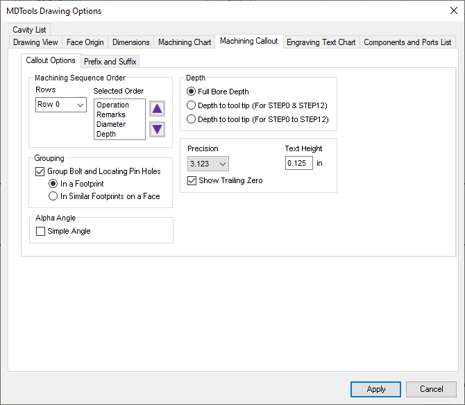
These options enable you to configure the output of the Machining Callout.
1. Specify the order of the machining sequence with the options available in the Machining Sequence Order group.
2. The Selected Order list shows the order in which the machining operation sequence are created for a particular row.
3. There are 7 row options available.
4. The order list is easily built by selecting a machining sequence row and clicking the up or down arrow button, in the desired order.
5. Select the number of decimal places for the Depth and Diameter entries in the callout from the drop down.
6. Specify the value of text height for the callout text.
7. Select the Show Trailing Zero option to display the trailing zero in the cavity diameter and depth.
8. Select Group Bolt and Locating Pin Holes to either group the Machining Callouts automatically for a Footprint or similar Footprints on a Face..
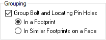
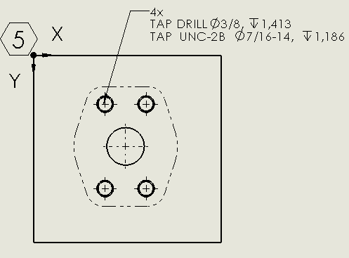
Machining Callout:Grouping of cavities within a Footprint
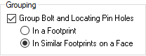
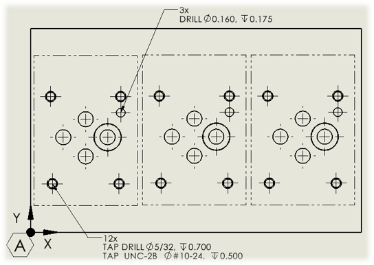
Machining Callout: Grouping of Cavities within multiple Footprints
9. Select the Simple Angle option to show the alpha angle for the simple angle holes in the machining callout.
10. Specify prefixes and suffixes for all the machining sequence rows and columns in the Prefix and Suffix tab.
11. Specify Angle Prefix for the Alpha and Beta angle to display in the machining callout.
For example, /Angle
12. Specify Angle Suffix for the Alpha and Beta angle to display in the machining callout. For example, Degree Symbol ° i.e 28°
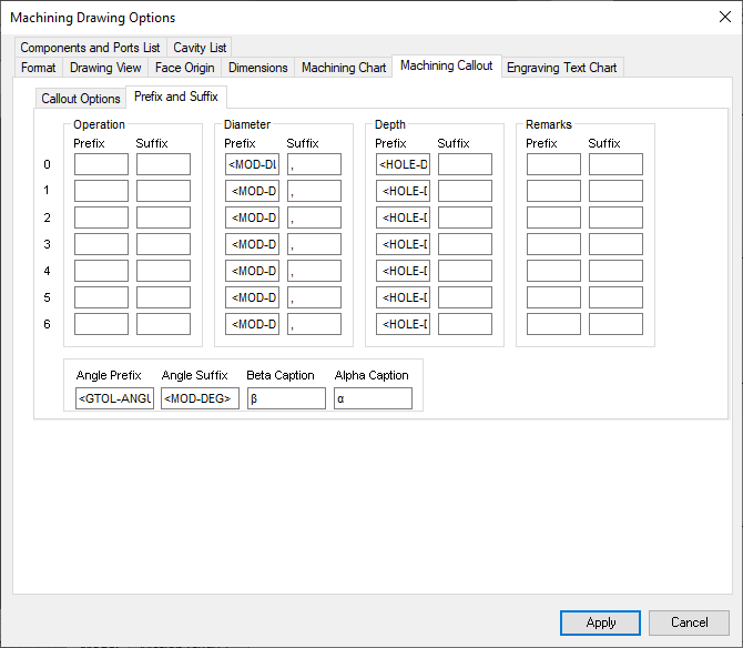
Machining Callout: Prefix and Suffix
13. Specify Beta Caption for the Beta angle in the machining callout. For example, Beta =
14. Specify Alpha Caption for the Alpha angle in the machining callout. For example, Alpha =
15. Click Apply to save changes.