Create/Modify Footprints
1. Select a Library to add or modify Footprints.
By default, *All* is selected.
Add option is enabled after selecting a library. Only cavities in the selected library display in the Cavities/Footprints list.
2. Select Cavity Type as Flange or Interface.
By default, *All* is selected. All type of cavities in the selected Library display in the Cavities/Footprint section.
3. Click the Add option, which is below the Cavities/Footprints list, to add new footprint.
or
Select a footprint from the Cavity/Footprint list to modify a footprint.
You can also search a footprint by entering the name of a footprint in the Cavity Name field.
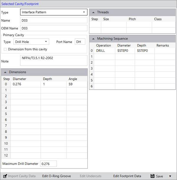
The Selected Cavity/Footprint section displays.
4. Enter/modify the main cavity details.
5. Select Footprint type Interface Pattern or Flange.
6. Enter Name and OEM Name of a footprint.
7. Enter Primary Cavity details.
The Primary cavity is created at the insertion point when the footprint is inserted on the manifold.
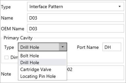
8. Select Primary Cavity Type.
For Interface Pattern, Primary cavity is one of the following type:
- Bolt Hole
- Drill Hole
- Cartridge Valve
- Locating Pin Hole
For Flange, Primary cavity is one of the following type:
- Bolt Hole
- Drill Hole
- Port
9. Enter the Port Application Name of the cavity in the Port Application Name field.
The port application name is automatically entered, depending on the type of the cavity.
You can edit the port application name,
if the cavity is a drill hole.
Port application name is the application name of the hole on the footprint.
For example A, B, T, and P are the application names of four working ports on a D03 footprint.
10. The Dimension from this Cavity option enables you to specify which cavity will be dimensioned in the block machining drawing, when you want to dimension only the reference cavity in a footprint.
Only one cavity in an interface pattern or flange is selected as Dimension from this Cavity. Other cavities get automatically deselected, if Dimension from this Cavity is selected for the Primary cavity option.
If other than primary cavity, the Dimension from this Cavity option is not selected. Then, Primary cavity is automatically selected.
11. Enter Cavity Geometry details.
12. Click Save to save the cavity data into the library.
13. You can Attach/Delete O-ring groove to a Drill Hole (DH).
· Click Edit O-ring Groove.
The Select O-ring dialog box displays.
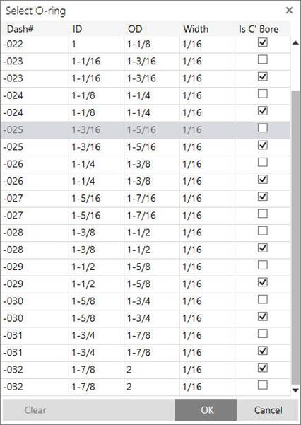
· Select the O-ring.
· Click OK to attach the selected O-ring groove corresponding to the O-ring.
If O-ring is already attached to a cavity, then it displays as a selected O-ring.
· You can delete attached O-ring using the Clear option.
12. Click Save to save the cavity data into the library.
Note:
· Save the main cavity into the library to create other cavities in the footprint.
· The O-ring Groove will not appear on the Cavity Preview in the MDTools Library Manager.
· The O-ring Groove is available only for Drill Holes (DH).